About the device – You can identify garments made of materials that cannot readily be detected by active IR presence sensors used on automatic swinging doors using the instrument described on this page, which you can build yourself. The fancy name for the device is an infrared (IR) reflectometer. However, it operates on a very simple principle, which duplicates the underlying principle of operation of the automatic door sensors at issue. Namely, it transmits pulses of IR light into the environment, and monitors the strength of the IR light reflected back from objects nearby.
The primary objectives in the design of the device described here were simplicity, absolute minimum cost and ready availability of components. Consequently, many improvements and new features can be thought of and added. They were omitted here in the interest of creating the simplest and least expensive device capable of reliably identifying materials that reflect poorly in the near infrared.
The device actually consists of two parts – an IR transmitter and an IR receiver – which can be readily built into a small plastic or aluminum box. A momentary-ON switch is used to activate the IR transmitter in order to make a measurement. When the IR receiver detects the IR reflected back into the device, a green LED (Light Emitting Diode) is illuminated in proportion to the strength of the reflected energy. The greater the strength of the reflected IR energy, the brighter the LED glows (LED1 in receiver section).
Using the device – The relative IR reflectance of any material or surface can be determined by pointing the device toward the target material from a short distance away and gauging the brightness of the green LED in comparison with other targets tested at approximately the same distance. The less brightly the LED glows, the more absorbing the target material, and the greater the likelihood that a person wearing the material will be struck by an automatic pedestrian door utilizing an active IR sensor of the type considered here.
The device also includes a sensitivity control. For comparisons to be meaningful, measurements must be made at a fixed common setting of the sensitivity control.
What to look for – You should examine first materials that appear jet black to the eye, and have a velvet-like surface texture. However, these characteristics are not a guarantee that the material will absorb heavily in the infrared, as you will quickly discover by using the device to make comparisons with other materials. It is also possible that materials that appear relatively bright to the eye (i.e., in the visible part of the spectrum), may, in fact, absorb heavily in the infrared. Therefore, such materials should not be overlooked in your tests.
See note below regarding Adobe Acrobat Reader and viewing PDF files.
Notes:
- Other IR LEDs may be substituted for LED3 and LED4.
- The choice, set by the Peak Wavelength switch, of two IR peak wavelengths (via LED3 and LED4) is optional.
- It is very important that the light radiated from LED3 and LED4 not be allowed to leak into the IR detector module used by the receiver. Adequate light baffling should be provided between LED3 and LED4 and the IR detector module in the receiver section.
- LED2 (red) indicates power on/off.
- Note that the +5V regulated supply for the receiver is shown in the transmitter section above.
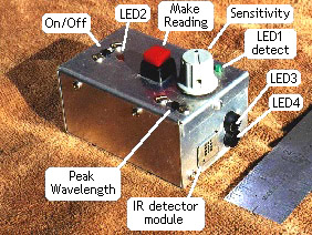 The completed IR reflectometer, showing the placement of the controls and indicators. Note
the small tubes, painted flat black, through which LED3 and LED4 emit IR radiation. Each
LED is located at the base of its respective tube, about 2 cm long, where it is sealed.
In this way, IR from LED3 and LED4 can exit only through the open ends of the tubes.
The completed IR reflectometer, showing the placement of the controls and indicators. Note
the small tubes, painted flat black, through which LED3 and LED4 emit IR radiation. Each
LED is located at the base of its respective tube, about 2 cm long, where it is sealed.
In this way, IR from LED3 and LED4 can exit only through the open ends of the tubes.
Note also that the open ends of the tubes project beyond the face of the IR detector module. This serves as well to minimize leakage of IR radiation from LED3 and LED4 back into the IR detector module.
The device diagrammed and pictured here is the one shown in the WCCO-TV I-team report by Jilda Unruh and used by Dr. Warren Davis to identify materials that are essentially invisible to automatic pedestrian door sensors of the subject type.